

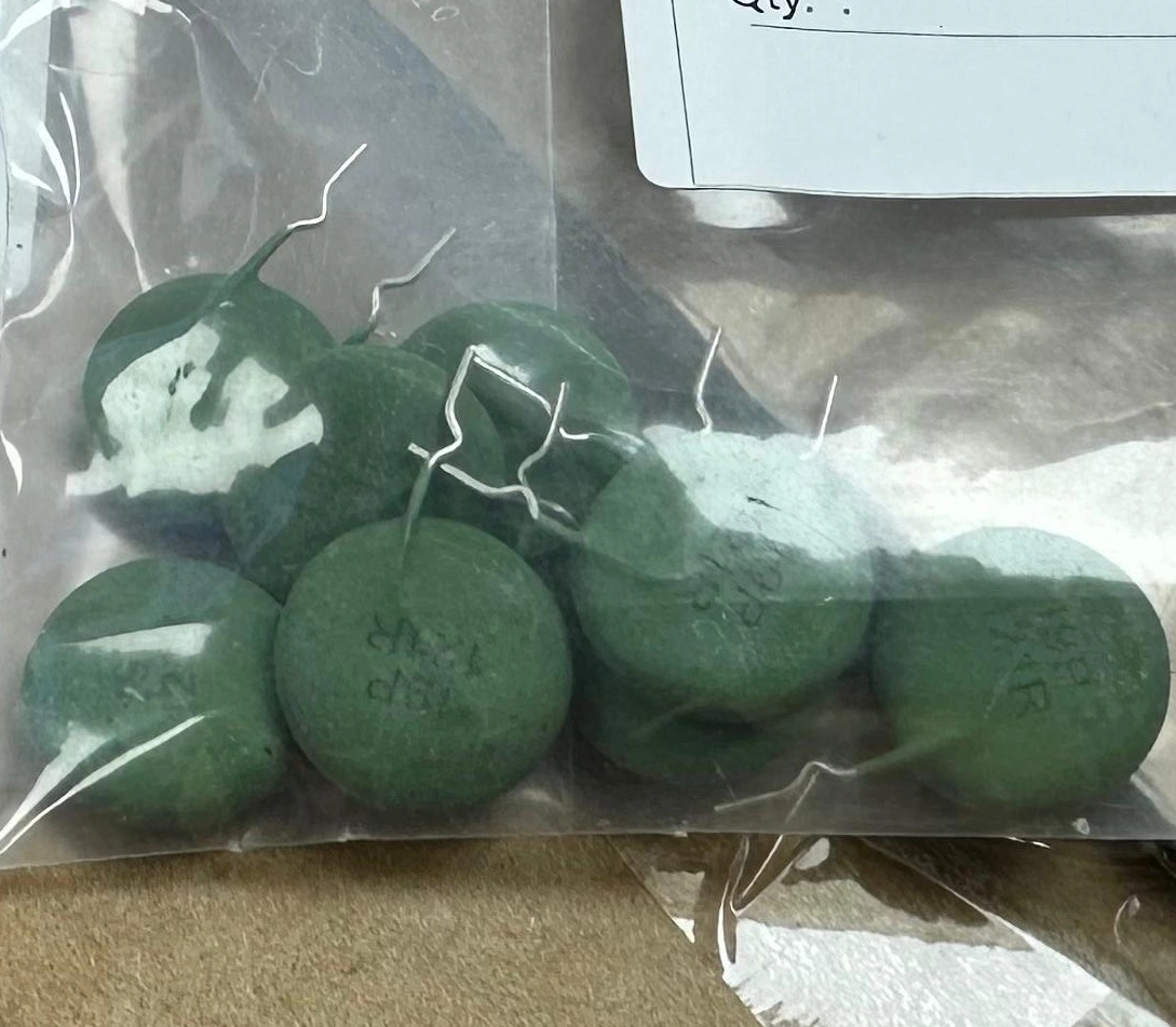
Inrush Current Limiter Design Guide (PTC 120Ω 440V)
Green
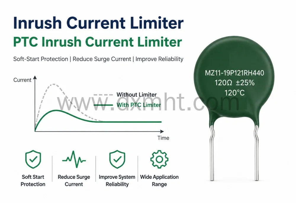
Inrush Current Limiter solutions are essential in modern power electronics. A PTC Inrush Current Limiter provides simple and reliable soft-start protection. It helps reduce surge current during startup and improves system reliability. Engineers often use this technology in power supplies, motors, industrial equipment, and capacitor charging circuits.
The MZ11-19P121RH440 is a ceramic PTC thermistor designed for soft start applications. It provides a rated resistance of 120Ω±25%, a Curie temperature of 120±7℃, a rated operating voltage of 380Vr, and a maximum operating voltage of 440Vmax. The device also withstands 800V for 15 seconds and stores up to 126J of energy. These specifications come directly from the product datasheet and remain unchanged.
Why Is Inrush Current a Problem?
Many electronic systems experience a large current surge when power is first applied. This current spike may exceed several times the normal operating current.
Large electrolytic capacitors behave like a short circuit during startup. Motors also draw heavy current before reaching normal speed.
Without Inrush Current Limiters, excessive current may damage:
- Rectifier bridges
- Switching MOSFETs
- Electrolytic capacitors
- Power relays
- Fuses
- PCB traces
Strong surge current reduces product life. It also increases repair costs. A PTC Inrush Current Limiter solves this issue with a simple passive component.
How Does a PTC Inrush Current Limiter Work?
A PTC Inrush Current Limiter uses positive temperature coefficient ceramic material.
At room temperature, resistance remains low enough for normal operation.
During startup, current rises rapidly. The ceramic body heats itself. Resistance increases sharply.
This automatic resistance increase limits current flow and protects the circuit.
No external controller is required.
The device works automatically and repeatedly.
PTC Inrush Current Limiter Overview: MZ11-19P121RH440
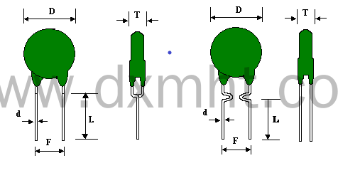
The MZ11 series PTC thermistor is developed for soft start applications. It uses silicon coating and in-form lead construction. The body diameter reaches 20mm maximum and thickness reaches 8.5mm maximum.
Mechanical Structure and Dimensions
Appearance Specifications
PTC ceramic structure with tin-plated copper leads. Two mounting types: axial and in-form.
|
Item |
Name |
Technical Requirements(mm) |
Leads |
|
D |
Diameter of PTC Inrush Current Limiter |
D:20.0max |
P-Tin-plated copper wire □Straight □Axis Formed ■In-Forming □out-formed |
|
T |
Thickness of Resistance |
T:8.5max |
|
|
L |
Length of fuse |
L:5.0±2.0 (Foot length can be adjusted according to requirements) |
|
|
F |
Distance between fuses |
F:7.5±1.0 |
|
|
d |
Diameter of lead wires |
d: 0.8±0.5 |
Part Numbering System
|
MZ11 19 P 121R H 440 1 2 3 4 5 6 |
MZ11 series defines structure, resistance, Curie temperature, and voltage class.
Each code segment maps directly to electrical parameters.
- Series:MZ11-series
- Diameter:06- 6.0mm 19-19.0mm
- Curie temperature:M-80℃ P-120℃
- Rated zero power resistance (RN) :121R-120Ω 681-680Ω 6R8-6.8Ω
- Tolerance: M-±20% H- ±25% N-±30% P-±35% X-Special
- Max Voltage:440-440V 265-265V
Main Technical Specifications of PTC Inrush Current Limiter
| Parameter | Specification |
|---|---|
| Part Number | MZ11-19P121RH440 |
| Application | Soft Start |
| Resistance | 120Ω ±25% |
| Curie Temperature | 120±7℃ |
| Rated Voltage | 380Vr |
| Maximum Voltage | 440Vmax |
| Over Voltage Withstanding | 800V / 15s |
| Heat Capacity | 3.0J/K |
| Maximum Non-Operating Energy | 126J |
| Operating Temperature | -20℃ to +85℃ |
Advantages of Using an Inrush Current Limiter
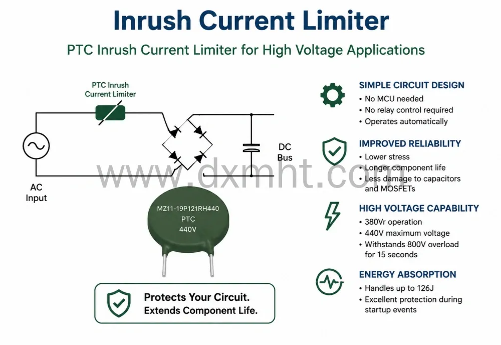
Simple Circuit Design
No MCU is needed.
No relay control is required.
The PTC Inrush Current Limiter operates automatically.
Improved Reliability
Lower stress means longer component life.
Capacitors and MOSFETs experience less damage.
High Voltage Capability
The MZ11-19P121RH440 supports 380Vr operation and 440V maximum voltage. It also survives 800V overload conditions for 15 seconds.
Energy Absorption Capability
The device handles up to 126J. This provides excellent protection during startup events.
Typical Applications
PTC Inrush Current Limiters are suitable for many industries.
- Switching power supplies
- Industrial control systems
- Motor start circuits
- LED drivers
- UPS systems
- Charging equipment
- Medical power supplies
- Welding machines
- Frequency converters
- Energy storage systems
Engineers often prefer a PTC Inrush Current Limiter when reliability is more important than complicated active circuits.
Engineering Example
Consider a capacitor charging power supply.
When AC power turns on, the capacitor behaves like a short circuit.
Without an Inrush Current Limiter, surge current may reach several hundred amperes.
Using MZ11-19P121RH440 reduces startup stress immediately.
As temperature rises, resistance increases rapidly.
Current becomes controlled.
This process protects bridge rectifiers and switching transistors.
Selection Guide for a PTC Inrush Current Limiter
Selecting the correct Inrush Current Limiter requires several factors.
1. Working Voltage
Always check the normal operating voltage.
The MZ11-19P121RH440 supports 380Vr and allows 440V maximum operation. It can withstand 800V for 15 seconds.
2. Resistance Value
Resistance determines the startup current.
This model provides 120Ω ±25%.
Higher resistance produces lower surge current.
3. Energy Capability
Capacitor charging circuits generate large energy pulses.
The device supports 126J non-operating energy.
4. Ambient Temperature
The operating range is -20℃ to +85℃.
PTC Inrush Current Limiter vs Active Soft Start Circuit
| Parameter | PTC Inrush Current Limiter | Active Soft Start |
|---|---|---|
| Circuit Complexity | Low | High |
| Cost | Low | Higher |
| Reliability | Excellent | Depends on controller |
| Maintenance | Minimal | Higher |
| External Components | No | Yes |
| Response | Automatic | Programmable |
Practical Experience from Engineers
In industrial power supplies, startup current often causes unexpected failures.
Many engineers focus only on MOSFET ratings.
They forget capacitor charging current.
Adding a PTC Inrush Current Limiter often solves repeated failures.
This method is common in UPS systems, LED drivers and industrial controllers.
Field experience shows that lowering startup stress improves system reliability.
It also reduces maintenance costs.
Mechanical and Reliability Characteristics
The MZ11-19P121RH440 uses silicon coating and in-form leads. It employs 0.8mm tin-plated wire.
The body diameter is 20mm maximum and thickness is 8.5mm maximum.
Solderability exceeds 95%.
Heat resistance testing follows GB2423.28 standards.
Lead strength testing follows GB2423.29 standards.
Resistance variation remains within 20% after testing.
Installation Recommendations
Install the PTC Inrush Current Limiters where airflow is available.
Avoid placing it close to heat-sensitive components.
Keep enough spacing around the ceramic body.
Use proper creepage distance in high-voltage applications.
Avoid continuous overload conditions.
Always verify capacitor energy before selecting the component.
Storage Conditions
Recommended storage temperature is -10℃ to +40℃.
Humidity should remain below 70%RH.
Shelf life is six months.
Avoid corrosive gases, oil, water and direct sunlight. After opening the package, reseal immediately and use a dry container for storage.
Why Engineers Choose MZ11-19P121RH440
- 120Ω resistance for soft start circuits
- 120℃ Curie temperature
- 380Vr rated operation
- 440V maximum working voltage
- 800V over-voltage capability
- 126J energy handling ability
- Reliable ceramic structure
- Long service life
- Simple circuit implementation
- Suitable for industrial applications
Related Products and Technical Resources
Learn more about PTC thermistors and soft start solutions:
Conclusion
Inrush Current Limiter technology remains one of the simplest ways to improve power supply reliability. Real-world experience shows that excessive startup current is a major cause of failures. Properly selected PTC Inrush Current Limiters can reduce electrical stress and extend system life. The MZ11-19P121RH440 combines 120Ω resistance, 120℃ Curie temperature, 380Vr rated voltage and 440V maximum voltage capability. It also offers 800V transient resistance and 126J energy handling capability. For engineers designing reliable soft-start circuits, an Inrush Current Limiter and a PTC Inrush Current Limiter remain practical and cost-effective solutions for industrial power systems.
Related Technical Articles
PTC Thermistor Manufacturer and Product Guide
PTC Thermistor Solutions from DXM
How to Select a PTC Inrush Current Limiter
NTC vs PTC Thermistor Comparison- © 2026 DXM Product. All rights reserved.
Author: Ivan
Updated on 20th June 2026
FAQ
What is an Inrush Current Limiter?
An Inrush Current Limiter reduces surge current during startup. It protects power devices and capacitors from excessive stress.
What is a PTC Inrush Current Limiter?
A PTC Inrush Current Limiter uses positive temperature coefficient ceramic material. Resistance increases automatically as temperature rises.
Where are PTC Inrush Current Limiters used?
They are widely used in switching power supplies, motor drives, LED drivers, UPS systems and industrial equipment.
What resistance does MZ11-19P121RH440 provide?
The nominal resistance is 120Ω ±25%.
What is the maximum operating voltage?
Maximum operating voltage is 440Vmax. Rated operating voltage is 380Vr.
Can it withstand transient overvoltage?
Yes. It withstands 800V for 15 seconds.
What is the operating temperature range?
The temperature range is -20℃ to +85℃.
How should the component be stored?
Store below 40℃ and below 70% humidity. Avoid oil, water and corrosive gases.
Get in Touch
Discover premium thermistors, sensors, and resistors tailored to your needs.Our dedicated team of experts is available to assist with product selection, technical queries, and after-sales service. Contact us for custom solutions and experience exceptional customer support.


© 2025 DXM | All Rights Reserved.
 Scan QR Code
Whatsapp: +8618927361658
Shenzhen DXM Technology Co., Ltd.
DXM PTCNTC
Shenzhen DXM Technology Co., Ltd