Metal Oxide Varistor Parameters and Testing Methods
Metal oxide varistors are essential components for protecting electronic circuits from surge current. Understanding their key parameters and testing methods is crucial for ensuring their reliability and effectiveness. By following the outlined testing procedures and selecting varistors with appropriate parameters, engineers and technicians can enhance the protection of electronic systems. Understanding the parameters and proper testing methods of MOV varistors is essential for their effective application. Key parameters include maximum clamping voltage, surge current capacity, leakage current, and nominal voltage. Testing methods involve varistor voltage testing, leakage current testing, clamping voltage testing, surge current capacity testing, etc.
- Varistor Parameters and Testing Methods
- What is a Metal Oxide Varistor?
- Applications of Metal Oxide Varistors
- Key Features of MOV Varistor
- Main Parameters of Metal Oxide Varistors
- Table of Key Parameters
- Varistor Testing Methods
- Introduction:
- Conclusion:
- Practical Testing Example
- Equipment Required:
- Steps:
- Conclusion

Varistor Parameters and Testing Methods
Metal oxide varistors (MOVs) are critical components in electronic circuits, serving as voltage protection devices. They protect sensitive electronics from voltage spikes by clamping high voltages and absorbing excess energy. Understanding the parameters and testing methods of MOVs is essential for ensuring their reliability and functionality in various applications. This article delves into the key parameters and testing methods for MOVs, providing a comprehensive guide for engineers and technicians.
Understanding the parameters and proper testing methods of MOV varistors is essential for their effective application. Key parameters include maximum clamping voltage, surge current capacity, leakage current, and nominal voltage. Testing methods involve varistor voltage testing, leakage current testing, clamping voltage testing, and surge current capacity testing.
What is a Metal Oxide Varistor?
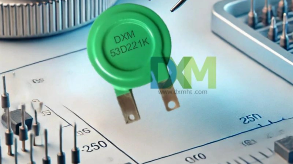
A metal oxide varistor (MOV) is a voltage-dependent, nonlinear resistor composed primarily of zinc oxide along with small amounts of other metal oxides. When subjected to a high voltage, the resistance of the varistor decreases significantly, allowing it to conduct a large current and thereby clamp the voltage to a safer level. This characteristic makes MOVs ideal for protecting electronic circuits from transient voltage spikes.

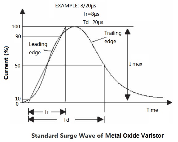
Standard Surge Wave of Metal oxide Varistor
Applications of Metal Oxide Varistors
MOVs are widely used in various applications to protect electronic circuits from surge current. Common applications include:
| Application | Description | Key Parameters |
|---|---|---|
| Lighting Products | Protects lighting systems from voltage fluctuations | Maximum Clamping Voltage, Leakage Current, Surge Capacity |
| Power Supplies | Converts electrical power for devices | Nominal Voltage, Insulation Resistance, Static Capacitance |
| Uninterruptible Power Supplies | Provides backup power and voltage regulation | Surge Current Capacity, Leakage Current, Voltage Ratio |
| Communication Products | Safeguards communication equipment | Clamping Voltage, Leakage Current, Insulation Resistance |
| TVSS Modules | Protects systems from transient voltage surges | Maximum Clamping Voltage, Surge Current Capacity, Leakage Curren |
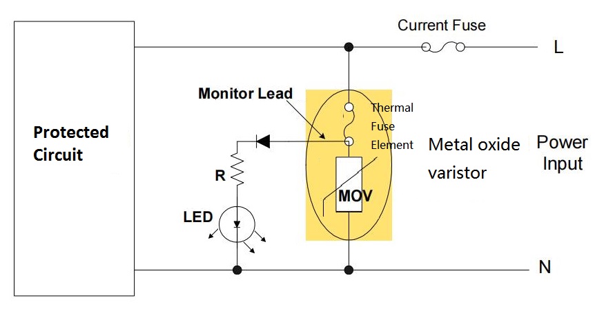
Application circuit of mov varistor

Key Features of MOV Varistor
Main Parameters of Metal Oxide Varistors
Understanding the parameters of metal oxide varistors is crucial for selecting the right varistor for specific applications. The key parameters include:
| Parameter | Description |
| Voltage Rating (V) | The maximum continuous voltage that the metal oxide varistor can handle without degradation. |
| Clamping Voltage (Vclamp) | The voltage level at which the mov varistor starts to conduct significantly, clamping the surge voltage. |
| Energy Rating (J) | The maximum energy the MOV can absorb in a single surge event. |
| Response Time (ns) | The time taken by the varistor resistor to respond to a transient surge, typically in nanoseconds. |
| Capacitance (pF) | The inherent capacitance of the metal oxide varistors, which can affect high-frequency signal integrity. |
Table of Key Parameters
| Parameter | Description | Significance |
|---|---|---|
| Maximum Clamping Voltage | Highest voltage varistor can clamp | Protects components from overvoltage |
| Static Capacitance | Inherent capacitance of the varistor | Affects response to fast transients |
| Nominal Voltage | Voltage at specified current (1mA DC) | Indicates operational voltage range |
| Residual Voltage Ratio | Ratio of residual voltage to nominal voltage | Determines clamping effectiveness |
| Leakage Current | Current flow under specified conditions | Desirable to minimize power loss |
| Surge Current Capacity | Maximum peak current for a defined waveform and duration | Indicates energy absorption capability |
| Insulation Resistance | Resistance between leads and insulating surface | Prevents leakage paths |
| Current Temperature Coefficient | Relative change in current with 1°C temperature change | Performance under different temperatures |
| Voltage Nonlinear Coefficient | Ratio of static to dynamic resistance | Reflects nonlinear clamping ability |
| Voltage Temperature Coefficient | Rate of nominal voltage change with temperature change | Important for varying temperature applications |
| Voltage Ratio | Ratio of voltage at 1mA to 0.1mA current | Indicates voltage sensitivity |
Varistor Testing Methods
Introduction:
Testing metal oxide varistors (MOVs) is crucial to ensuring their effectiveness in protecting electronic circuits. This guide outlines the primary methods for testing MOVs, detailing the necessary equipment and procedures.
| Testing Method | Equipment | Procedure |
| Varistor Voltage Testing | DC power supply, microammeter | Apply a steady DC voltage to the varistor and measure the voltage across its terminals when a 1mA current flows through it. This measured voltage is the varistor voltage. |
| Leakage Current Testing | DC power supply, microammeter | Apply the maximum rated DC voltage to the varistor and measure the current that flows through it. This current is the leakage current. |
| Clamping Voltage Testing | Surge generator, oscilloscope | Apply a surge voltage to the varistor and measure the peak voltage across its terminals. This peak voltage is the clamping voltage. |
| Surge Current Capacity Testing | Surge generator, current probe | Apply a defined surge current waveform to the varistor and measure the peak current it can withstand without failure. This peak current is the surge current capacity. |
| Insulation Resistance Testing | Megohmmeter | Measure the resistance between the varistor's leads and its insulating surface. This resistance should be high to ensure no leakage paths. |
| Temperature Coefficient Testing | Temperature chamber, voltmeter, ammeter | Measure the varistor voltage and leakage current at different temperatures to determine the temperature coefficients. |
Conclusion:
Proper testing of metal oxide varistors ensures the reliability and longevity of your electronic circuits. By following these outlined methods, you can effectively evaluate the performance of your varistors and maintain the safety of your electronic systems.
Practical Testing Example
Let's consider a practical example of testing a variable's parameters using the above methods.
Equipment Required:
- DC power supply
- Microammeter
- Surge generator
- Oscilloscope
- Megohmmeter
- Temperature chamber
Steps:
-
Varistor Voltage Testing
- Connect the varistor to the DC power supply and microammeter.
- Increase the voltage gradually until the current through the varistor reaches 1mA.
- Record the voltage at this point as the varistor voltage.
-
Leakage Current Testing
- Apply the maximum rated DC voltage to the varistor.
- Measure the current flowing through the varistor using the microammeter.
- Record this current as the leakage current.
-
Clamping Voltage Testing
- Connect the varistor to the surge generator and oscilloscope.
- Apply a surge voltage and observe the peak voltage across the varistor on the oscilloscope.
- Record this peak voltage as the clamping voltage.
-
Surge Current Capacity Testing
- Connect the varistor to the surge generator and current probe.
- Apply a surge current waveform and measure the peak current using the current probe.
- Record this peak current as the surge current capacity.
-
Insulation Resistance Testing
- Connect the varistor to the megohmmeter.
- Measure the resistance between the varistor's leads and its insulating surface.
- Record this resistance as the insulation resistance.
-
Temperature Coefficient Testing
- Place the varistor in the temperature chamber.
- Measure the varistor voltage and leakage current at various temperatures.
- Calculate the temperature coefficients based on these measurements.
Conclusion
Metal oxide varistors are essential components for protecting electronic circuits from surge current. Understanding their key parameters and testing methods is crucial for ensuring their reliability and effectiveness. By following the outlined testing procedures and selecting varistors with appropriate parameters, engineers and technicians can enhance the protection of electronic systems.
You may also like

Disk Varistor 05D series: Advanced Solutions for Effective Surge Protection

metal oxide varistor 10D series

MOV Varistor 14D Series : Essential Metal Oxide Varistor Surge Protection

Zinc Oxide Varistor 34S:Reliable for Surge Protection
Get in Touch
Discover premium thermistors, sensors, and resistors tailored to your needs.Our dedicated team of experts is available to assist with product selection, technical queries, and after-sales service. Contact us for custom solutions and experience exceptional customer support.
© 2025 DXM | All Rights Reserved.

 Scan QR Code
Scan QR Code
Whatsapp: +8618927361658
Shenzhen DXM Technology Co., Ltd.
DXM PTCNTC
Shenzhen DXM Technology Co., Ltd